On June 21, at the 2025 SMM (4th) Electric Drive System Conference & Drive Motor Industry Forum - Automotive Electric Drive System Forum, jointly hosted by SMM Information & Technology Co., Ltd. (SMM), Hunan Hongwang New Material Technology Co., Ltd., Louxing District People's Government, and the National-level Loudi Economic and Technological Development Zone, Zhong Jingwen, an expert in drive modules from Joyee Powertrain Systems Co., Ltd., shared insights on the topic of "Technology Development Plan for Electric Control Inverter Bricks."
I. Inverter Brick Planning
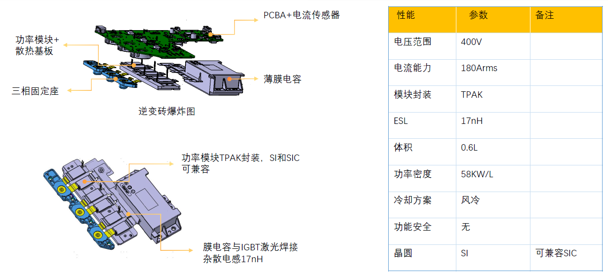
II. Inverter Brick Gen1 Display
Inverter Brick Gen1 Display (Low Power Segment TPAK)
He also analyzed content such as Inverter Brick Gen1 Display (Medium Power Segment TPAK Parallel), Inverter Brick Gen1 Display (High Power Segment HPD), and Inverter Brick Gen1 Display (Dual Electric Control).
III. Inverter Brick Gen2 Display
Inverter Brick - Gen2 Demand Analysis
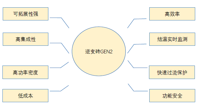
Requirements for Gen2 Inverter Brick Performance Improvement:
• Low stray inductance to reduce switching losses and adapt to SIC applications;
• Platform-based design with high compatibility (voltage platform, SIC & IGBT);
• Improved accuracy and effectiveness of junction temperature monitoring;
• Rapid overcurrent protection to adapt to SIC applications;
• Efficient heat dissipation and high power density;
• Enhanced temperature resistance of the power module junction;
• Cost optimization.
Inverter Brick - Gen2
Medium Power Platform Inverter Brick (<150kW):
• Compatible with 400V and 800V platforms;
• Compatible with IGBT and SIC power modules.
High Power Platform Inverter Brick (<250kW)
• Compatible with 400V and 800V platforms;
• Compatible with IGBT and SIC power modules.
Inverter Brick Gen2 - Low Stray Design and Integrated Capacitor Potting
Low Stray Design: Optimized busbar and core design for DC-Link capacitors, with stray inductance controlled at <2nH; laser welding process used for power module terminal connections, with overall stray inductance controlled at <5nH.
Integrated Capacitor Potting: DC-Link capacitors and housing water channels are integrally potted, effectively reducing costs, minimizing size, and enhancing core heat dissipation capabilities.
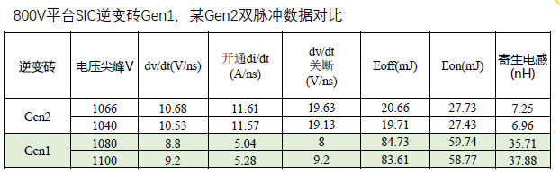
• The stray inductance of the Gen2 inverter brick system can be reduced to 8nH, a 75% decrease compared to Gen1; under the same voltage critical peak, switching losses are reduced by 70%, significantly improving the efficiency and output capacity of SIC modules.
Inverter Brick Gen2 - Power Module
Integrated Coreless Current Detection: A coreless detection scheme is used for three-phase current sampling, eliminating traditional cores and effectively reducing sensor costs; the reduction in core size and the use of laser welding for three-phase copper busbars can effectively shorten the three-phase terminal dimensions.
Compatibility: IGBT and SIC package compatibility; 800V and 400V platform package compatibility.
High-power platform - HPD G3: 470V@≥560Arms; 900V@≥460Arms; Tjmax 185°C@SIC.
Medium-power platform - HPD SMALL: 470V@≥560Arms; 900V@≥320Arms; Tjmax 185°C@SIC.
On-chip temperature detection support: Supports on-chip temperature detection capability, enabling rapid, direct, and effective junction temperature monitoring and protection execution.
On-chip overcurrent detection support: SIC modules have weaker short-circuit withstand capability; supporting on-chip overcurrent detection allows for rapid protection against overcurrent and short-circuit conditions.
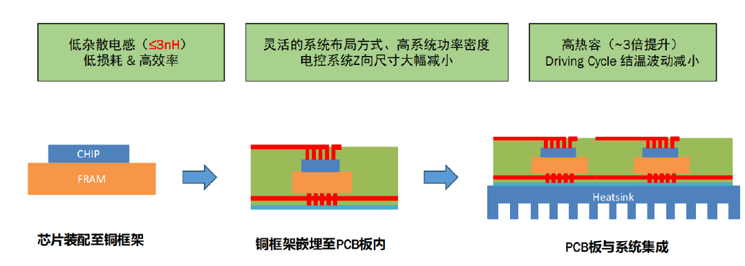
Inverter Brick Gen3 Display (PCB Embedded Packaging Technology)
Introduction to Technical Solution:
The stray inductance of the embedded module is approximately 3nH, the stray inductance of the embedded system is approximately 6-8nH; the stray inductance of the HPD package is approximately 8-10nH; the stray inductance of the HPD system is approximately 25nH-30nH.
Dynamic losses are reduced by approximately 50% compared to the HPD system, with a 20% increase in current output for the same chip area.
Total module cost: Embedded packaging can reduce costs by approximately 10-20%, primarily due to savings in chip area. (Prerequisite: Improvement in PCB embedding process yield to reach conventional PCB mass production yield levels.)
Electric control system cost: With increased power density and integration, there is an opportunity to further reduce the cost of the electric control system.
Inverter Brick Gen3 Display (PCB Embedded Packaging Technology)
Click to view the 2025SMM (4th) Electric Drive System Conference & Drive Motor Industry Forum Report Special